
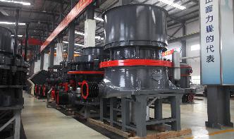
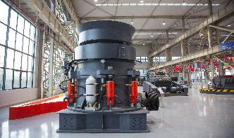
S Ew Palnt Process Schematic
gold processing plant schematic
gold processing plant schematic (SCN ) from gold mining tailings water UoM Commercial. Robust and flexible membranes withstand industrial processing Schematic of the gold extraction process ...
Processing Gold Processing Plants Schematics
Processing Gold Processing Plants Schematics. The process design of gold leaching and carbon in pulp,currently operating plant. process overview and description the cip process blockflow diagram of a typical cip plant for a nonrefractory gold ore is shown in figure table and table II illustrate the capital and operating cost breakdowns for a typical south african gold plant. these figures ...

Process Flow Diagram Software
A process flow diagram (PFD), also known as a flowsheet, is a type of flowchart used by chemical and process engineers to illustrate highlevel processes. You should create your process flow diagram so that it focuses on major plant processes and not show minor details.

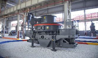
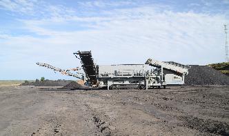
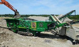
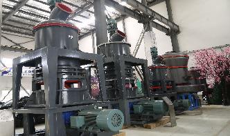
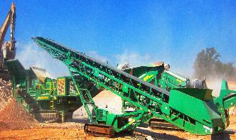
Small Scale Gold Processing Palnt
Small Scale Gold Processing Palnt. SBM s Gold Processing Plant For Sale SBM developed complete sets of mobile gold processing plant which can be equipped with crushing plant screening machine and separation equipment etc It can be easily move on the working site The mobile processing plant capacity ranges from 100tph2500tph for different scale production appliions.
Diagram of ActivatedSludge Process
On the following picture you see a schematic diagram of an ActivatedSludge System. This system is usually placed between the primary clarifier and the disinfection of a municipal wastewater treatment plant. A Flow Diagram of a Municipal Wastewater Treatment Plant with a suspendedgrowth process, gives you a better picture of the whole process ...
Ethylene Production Plant Design
An ethylene production plant was designed to meet a product speci ion of 700 metric tons per day. To do so, 140,010 lb/hr of butane is fed to the plant, and of ethane is recycled at a rate of 8,174 lb/hr. This plant process includes: a furnace (to crack the hydrocarbon
Wet Process of Cement Manufacturing
Wet process cement manufacturing method can be used to produce various types of Portland cement, such as ordinary Portland cement, white Portland cement, oil well cement, etc. It can help your cement plant to achieve high quality and high output cement production.
Hydro Electric Power Plant
Hydro Electric Power Plant: Here I am going to explain you the different types of power generating stations or power, let us know what is the function of a power generating power generating station or power plant uses various sources like hydel energy, thermal energy, diesel, nuclear energy to produce bulk electric now we going to discuss only Hydro electric ...
Engineering Schematics | Plant Design Software Solutions ...
Engineering Schematics. To keep a plant operating smoothly over its 30 to 40year life requires efficient and intelligent plant engineering from the beginning. Hexagon's PPM division comprehensive plant design software has been developed for today's 24/7 global engineering workshare environment. All engineering disciplines are intelligent ...
BIOWIN SOFTWARE FOR PROCESS MODELING GENERAL .
BIOWIN SOFTWARE FOR PROCESS MODELING GENERAL INSTRUCTIONS The software BioWin is installed on the Bechtel Computing Lab computers. Access from the Programs menu: "BioWin" "BioWin 3" Select the "Configure" tab to draw the plant schematic and specify element characteristics.
HACCP Form #4 Plant Schematic Question
· HACCP Form #4 Plant Schematic Question posted in Buildings Design Construction: Question Our facility is two separate buildings (approx 180,000 sq ft) but we have product piping to/from both buildings. Our product is liquor based, so very VERY low risk of any sort of micro or bacteria and there isnt really a required pathway from raw to finished goods, as we have GMP throughout all ...
Coconut Oil Manufacturing Process With Flowchart
Coconut Oil Production Plant Process Step 1: Cutting. A coconut cutter is helpful in cutting large coconut pieces into smaller pieces. Our coconut cutting machine has a sharp round blade which makes cutting easier and faster. Step 2: Drying. The copra dryer is designed to convert coconut into copra.
Top 10 Tips for Professional Schematic Design | EAGLE | Blog
Pro Tip #4 – Make Sure Every Part Has a Unique Designator. This is another tip to enhance the consistency and readability of your schematic. Every symbol on your circuit needs to have its own unique designator so that every part is easily identifiable. For example, every resistor should follow a consistent naming sequence of R1, R2, R3, etc.
Process Flow Diagram
Plant design basis. The PFD shows the plant design basis indiing feedstock, product, and mainstream flow rates and operating conditions. 2. Scope of process. The PFD serves to identify the scope of the process. 3. Equipment configuration. The PFD shows graphically the arrangement of major equipment, process lines, and main control loops. 4.
Hydraulic and Pneumatic PID Diagrams and Schematics ...
A schematic diagram uses symbols to show the elements in a system. Schematics are designed to supply the functional information of the system. They do not accurately represent the relative loion of the components. Schematics are useful in maintenance work, and understanding them is an important part of troubleshooting.
Lubricants greases manufacturing plants Optimize and ...
Process Control Cellier Activity has developed Lubcel™, a specific process control software for lubricants and grease manufacturing plants helping you to achieve the compliance with quality procedures and a total traceability of operations. 3D view of a grassroot plant
Flow Diagrams of Sewage Treatment Plants | Waste Management
Flow diagrams of typical sewage treatment plants incorporating different processes or units are shown in Figs., and The sewage treatment plant shown in Fig. consists of Imhoff tanks and low rate trickling filters, and is suitable for small towns or cities.
Plants and equipment for processing milk powders – GEA
Manufactures expect reliable, hygienic equipment and plants that process high quality milk powders with exactly the right chemical composition and physical characteristics. Contact us Get a quote Dairybased milk powders offer shelfstable, nutritious options that can be used as an alternative to fresh milk, as a healthy, instant drink, or as ingredients in a wide range of recipes.